

Product Details
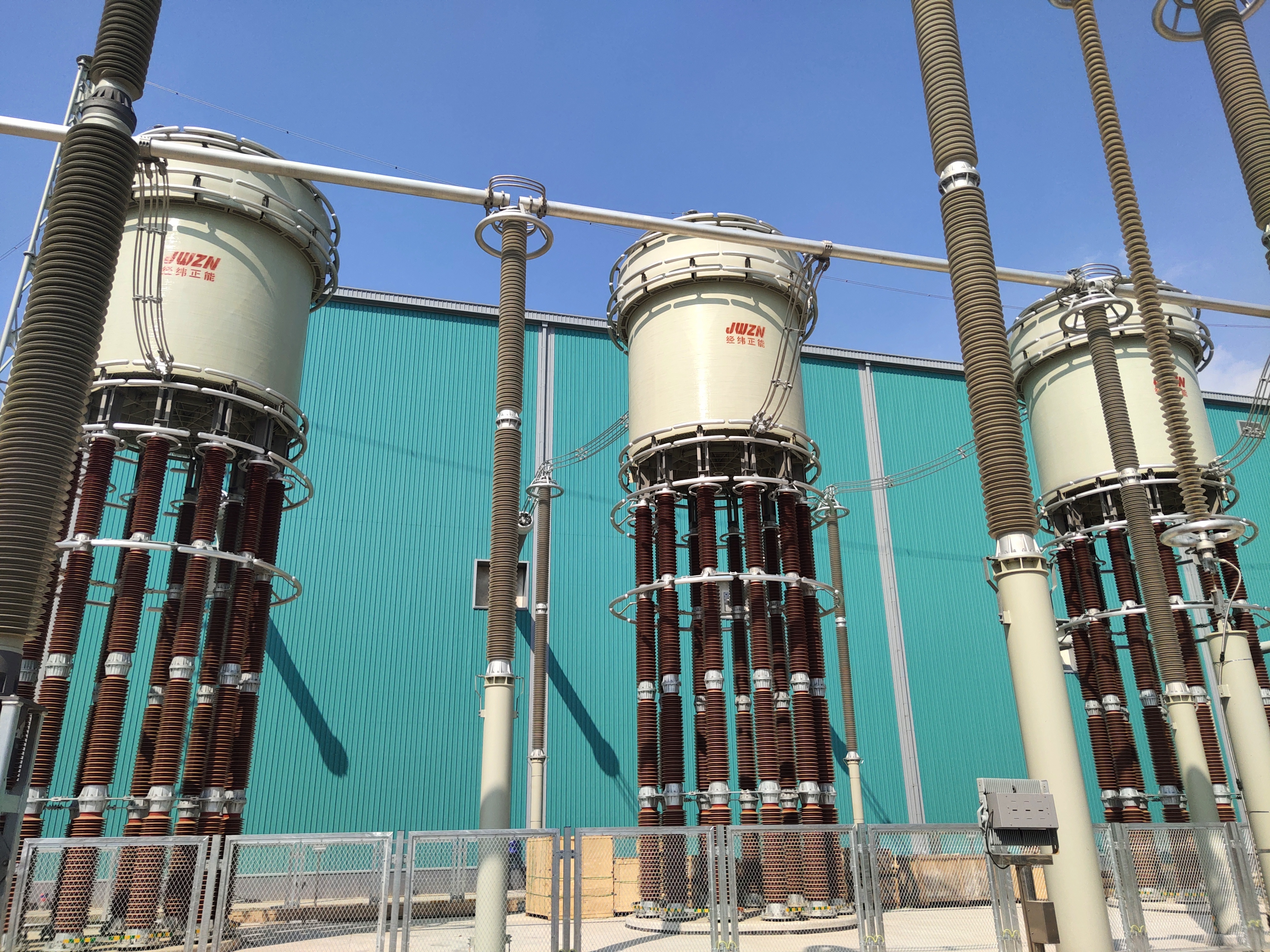
Converter reactor
The converter reactor is located between the flexible DC converter valve and the connecting transformer. It can be installed on either the DC side or the AC side of the converter valve.
Key words:
Converter reactor
Category:
E-mail:
Details
Converter Reactor
Rated Voltage: Up to 800 kV
Functional Role in HVDC Systems
Positioned between the flexible DC converter valve and connecting transformer (installable on DC/AC side), it forms the commutation reactance with transformer leakage reactance.
Key functions:
1.Power Flow Control: Regulates active/reactive power transmission
2.Harmonic Filtering: Suppresses AC-side current fluctuations (2nd-50th order)
3.Fault Current Limiting:
Controls di/dt during bridge arm commutation failures
Caps short-circuit current rise rate (<5 kA/ms typical)
Dynamic Stability: Damps sub-synchronous oscillations (SSR)
System Integration:
Integration Point | Key Parameters | Performance Impact |
|---|---|---|
DC Valve Side | • di/dt limit: ≤3 A/μs | Protects IGBT valves from overcurrent |
AC Transformer Side | • THD reduction: ≤1.5% | Improves grid power quality |
Commutation Loop | • L<sub>total</sub> = L<sub>reactor</sub> + L<sub>xfmr-leak</sub> | Determines overlap angle (μ) & fault tolerance |
Technical Specifications:
| Category | Standard Design | Customization Options |
| Electrical | • BIL: 2100 kV (LI) • SIL: 950 kV (SI) • Losses: ≤0.15% at full load | Adjustable reactance taps (±10%) |
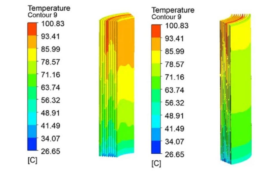
| Thermal | • Temp rise: 65K (winding) • Cooling: ONAN/ONAF | Forced-oil cooling (OFAF) for compact install |
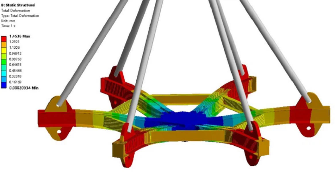
| Mechanical | • Sound level: ≤75 dB(A) @ 1m • Vibration: ≤100 μm pk-pk | Silenced enclosure (60 dB) option |
| Insulation | • RIV: ≤500 μV • C<sub>winding</sub>: 5-10 nF | SF<sub>6</sub>-gas insulation for extreme pollution |
Send Inquiry
We will contact you within one working day. Please pay attention to your email.
Related Solutions

Address: 902-903, Building 1, Yard 15, Xinya Street, Daxing District, Beijing, China


Feedback
Please fill out this form and we will contact you on the next business day.